VMU Power Supply Mod
The VMU for the Sega Dreamcast can be modified to accept as a power source an alternative to the pair of CR2032 batteries the VMU is designed for such as AA batteries or an AC adapter that supplies 6V of direct current. The new power source can be soldered directly to the VMU, or a common connector can be soldered to the VMU to enable you to detach the new power supply.
Basically all we'll be doing is soldering the positive and negative ends of our new power source to the corresponding terminals of the VMU. Now, there are two ways to go about this: one is invasive and involves drilling and soldering directly to the VMU's board, and the other involves soldering directly to the battery terminals, which doesn't even require you to open the VMU. The former method will result in a better looking VMU, but the latter is easier, less risky, and entirely reversible. This guide will cover the second, easier method.
This guide assumes you are somewhat familiar with working with electronics and that you know how to solder, strip wires, use a multimeter, and all that.
Tools needed:
- Small phllips head screwdriver
- Soldering iron
- 6VDC power source
- Voltmeter (optional but recommended for troubleshooting)
Contents
Step 1 - Selecting a Power Source
Batteries
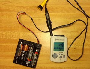
Standard alkaline batteries (AA, AAA, C, D, etc.) can be used to power the VMU if 4 of them are used together. Since each alkaline battery generates 1.5V, putting 4 in series will generate 4*1.5V = 6V of DC current. It would be easiest to do this mod for AA or AAA batteries since it is not dificult to obtain an enclosure which holds 4 of one of those types.
Rechareable Ni-MH AA or AAA batteries may not be able to power a VMU unless 5 are used in series since a typical rechargeable battery only generates 1.2V. This information needs to be verified.
AC Adapter
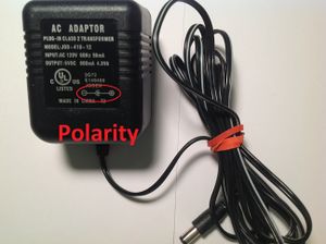
You may be able to power your VMU using a generic AC adapter if it meets the following criteria:
- It must output 6V of direct current (DC)
- It should be capable of outputing up to at least ~340mA of current It may require less current than that, but that is the lowest amount I've been able to experiment with.
If you choose to use an AC adapter, pay attention to the polarity of the cord. It's usually indicated on the front of the AC adapter, but if not you can use a voltmeter to determine the polarity.
Detachable cable (HIGHLY RECOMMENDED!)
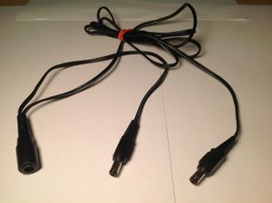
To do this mod right, you should attempt to track down a cord similar to the one pictured to the side. What it is is an extension cord that takes a cylindrical AC adapter's cord and splits it into two wires. What this cord will enable you to do is solder the female end to the VMU and use the male ends to modify a battery pack or AC adapter (if necessary) so they can plug into the female end. This will allow you to detach your new power supply from the VMU when you're not using it and to switch between AC power and battery power as you please.
If you decide to use an AC adapter with this cord, you should first identify its polarity (see above) and then use a voltmeter on the extension cord to figure out which wire corresponds to which part of the plug. This is so that when you solder the female end to the VMU you will not mix up positive and negative. If you're only using a battery pack, you can choose your polarity; just make sure you're consistent with both the female end (VMU side) and male end (battery side).
Step 2 - Solder the wires
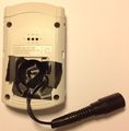
Once you've decided on a power supply and you've identified which end of it is positive and which is ground, it's time solder. Flip over the VMU and remove the battery cover and the two CR2032 batteries to expose the battery terminals. The large blade on the bottom is the negative end and the small blade off to the side is the positive end (see pictures below).
All you need to do is solder the wires of your power supply to the correct terminals of the VMU. If you're going to directly attach the supply to the VMU, make sure you give yourself plenty of cord length. If you use an extension cord to create a detachable plug, make it just long enough so that the thick end of the cord won't interfere with plugging the VMU into the first slot of a controller with something else in the second slot. With this mod, you will not be able to attach the VMU to the second slot any longer.
All that's left to do is test the VMU and seal off the battery compartment. Insert some fresh batteries or plug the AC adapter into the wall and see if the VMU powers on. It should spring to life with a long ear-piercing beep as soon as it receives power; you shouldn't have to press the mode or sleep buttons to get it to work. If it doesn't work, here are some tips to help you identify the problem:
- With the VMU receiving power, use a voltmeter to check the voltage at the solder points to confirm that you get 6V there. If you don't, then there is problem with the connection. Check the wires the continuity.
- If you're using batteries, make sure they are new and each outputting close to 1.5V. Batteries steadily decrease their voltage output as they are drained, so even a couple partially drained batteries could keep the VMU from powering up.
- If you're using an AC adapter, double check that the AC adapter itself is functioning with a voltmeter.
- If you've previously opened the VMU, the battery terminal blades may not have been properly reconnected to the circuit board. Open the VMU and make sure the terminals are tightly screwed into the board so that a connection is being made.
When everything is confirmed to be working, use some electrical tape or hot glue to seal off the battery compartment. It won't look pretty, but that's the price for functionality.


